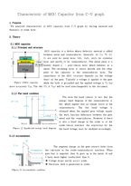
2.3 C-V graph
The measured MOS capacitance (called gate capacitance) varies with the applied gate voltage.
① Measurement of C-V characteristics
-Apply any DCbias, and superimpose a small (15 mV) ac signal
-Generally measured at 1 MHz (high frequency) or at variable frequencies between 1KHz to 1 MHz
-The dcbias VG is slowly varied to get quasi-continuous C-V characteristics
② C-V chara
A Light emitting diode (LED) is essentially a p-n junction diode. When carriers are injected across a forward-biased junction, it emits incoherent light. Most of the commercial LEDs are realized using a highly doped p-n Junction.
Mismatch between the sapphire substrate and the epilayer
Bending of the structure due to the thermal coefficient difference
Leakage by the strong electric current
Pr
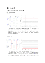
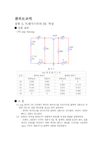
BJT I-V 특성 측정 회로의 시뮬레이션이다. 앞에서와 마찬가지로 가변저항은 저항하나로 대체했다. 콜렉터 이미터 전압에 따른 콜렉터 전류를 확인하는 시뮬레이션이다.
그러나 역시 실험(나)와 마찬가지로 시뮬레이션에 실패했다. 이론적으로 전압과 전류가 비례하는 것을 알기에 비례하는 그래
이번 실험의 목적은 순방향 및 역방향 바이어스가 이미터-베이스 전류에 미치는 영향을 측정하는 것이었다. 단자가 세 개이므로 하나의 단자를 공통으로 써서 회로를 구성하였으며 이럴 경우 내부 물리적 현상에 의한 실험 결과를 수치로 확인하는 과정이었다.
특히 이번 실험에서 사용된 실험도
A. 서론
Amplifier를 다음의 설계조건에 맞추어 설계하는 것이다.
① DC Gain = 100 V/V (40 dB)
② Slew Rate = 100 V/μs
③ Bandwidth = 5 MHz
④ LF = 100 kHz
⑤ VOP-P = 3 VP-P
⑥ Power Consumption < 2 mW
⑦ VDD = ± 2.5 V or 5 V
⑧ CL = 1 pF
⑨ RS = 50 Ω
먼저 우리는 책과 논문에 있는 amplifier들을 참조하여 여러 amplifier를 설계했다